Showing posts with label Projects. Show all posts

Friday, April 12, 2019

What I Have Been Up To

Over the past several years I have not been good about posting about the projects I have been working on.  This post is a high level overview of what I have been up to.

Home Automation (September 2016)

In September 2016 I setup a Raspberry PI 3 B+ running Domoticz with a Aeon Labs Z-Stick Series 2 USB device to support Home Automation.  My setup is very simple. 

I have four Ecolink Z-Wave Motion Sensors, three Leviton Z-Wave Smart Plug-In Dimmers, one GE Z-Wave 3 Way Dimmer Switch, one GE Z-Wave In-Wall Smart Switch and an Everspring Siren.  The system is setup to turn lights on and off at certain times and act as an alarm system when we are not home.

Domoticz was easy to setup, simple to use and very reliable.  In the two and a half years I have been using it the system has no hung or crashed.

When I started Domoticz I used the built in timers for the lights and LUA scripting for the security system.  Since the original installation I have upgraded Domoticz which added Python scripting which I am using for some of the newer automation.

I would highly recommend Domoticz for anyone looking for reliable and easy to use home automation.

Home Server Upgrade (September 2017)

Back in March of 2015 I shared setting up a home server using a pcDuino3 Nano and OpenMediaVault.  In September 2017 after successfully running that home server for two and a half years I migrated to an ODROID-HC1 running OpenMediaVault.  This setup has performed admirably since then.  Based on my experience I would recommend both the ODROID-HC1 and OpenMediaVault for use as a home server.

Home Music Center Upgrade (December 2017)

In December 2015 I shared setting up a Raspberry PI Music Player.  In December 2017 I migrated from my Raspberry PI running the Rune Audio Player to a Raspberry PI running MPD controlled by MPD clients on our cell phones.  This setup allows everyone in the house to control the music and has worked quite well.  I had to build a web based interface using lirc to control power and volume on the stereo receiver that powers speakers throughout the house.  The new setup has worked quite well.

Internet Bandwidth Monitor (October 2018)

Many years ago when I migrated from Comcast to Verizon Fios one of the things that I lost was the ability to monitor Internet utilization at my home. 

My Comcast cable modem supported SNMP and I had setup a script that ran every five minutes that queried the appropriate MIBs and then graphed the data using MRTG.  The Fios router doesn’t support SNMP so the way I was monitoring the bandwidth couldn’t be setup the same way.  I eventually found that I could telnet into the Fios router and pull down utilization data.  However, some where along the way a router upgrade broke that feature.

Late in the summer of 2018 I started looking at browser automation and discovered the ability to script a headless instance of a browser to scrape data off web pages  I started out using PhantomJS which I found was easy to use but also found out that development had been suspended in March.  I ended up using Headless Chrome and Selenium with a Python script to scrape the utilization data off the Fios router.

I had started this project on a Raspberry PI 3 B+ but found that the process didn’t run well on that platform and I ultimately had to move it to my much more powerful Windows desktop.  Once the data is scraped off the web page I store it in an InfluxDB from which I drive dashboards using Grafana.

The InfluxDB and Grafana are running on my ODROID-HC1 / OpenMediaVault home server as Docker containers using the OpenMediaVault Docker Plugin.

The whole setup has been running quite well for the past six month and I am once again able to see how much bandwidth is being consumed on my Internet connection.

House Temperature Monitor Prototype (November 2018 - March 2019)

Back in May of 2016 I shared my initial experiences with the Particle Photon.  I was very impressed with the photon and Particles platform.  So when they announced in their Particle Mesh devices for pre-order in February 2018 I decided to an Argon and four Xenons. 

Flash forward to the fall of 2018 and the Paticle Mesh boards arrive and I decide to build a simple monitoring device that would upload the temperature to a service which would allow it to be monitored from a remote location.  The beauty of using the Particle devices was that the device could be prototyped using an Argon and connect over wifi but could be deployed using the Boron and connect over LTE.  This would allow it to support monitoring where there wasn’t wifi.

The resulting prototype consisted of an Argon, an I2C VME280 temperature sensor, an I2C 128x64 OLED display and a Lipo battery in a plastic case with four buttons.  Using the firmware on the Argon uploads the temperature every five minutes to the Particle Cloud which creates a webhook to ThingSpeak where the temperature and humidity are presented in both graph and gauge form.

The prototype device has been sitting on my desk uploading data ThingSpeak consistently for the past two months.

I have a number of ideas that I hope to incorporate in a subsequent prototype and hope to document in more detail some of the useful lessons I learned along the way.

Saturday, February 4, 2017

Another Adventure with IOT - CallerID Project

Over the past year or so I have been looking for an IoT project.  Last summer I came up with one which was to capture caller id information and display it on our multiple computers around the house so we can see who is calling with out getting up and checking the phone.

image

For the project I used the opensource Mosquitto MQTT Broker running on a Raspberry PI configured with self signed certificates.  I used TLS connections with usernames and password to secure communications between the nodes.

I captured the caller id using an old US Robotics Sportster modem connected to an original Raspberry PI Model B using a serial to USB adapter.  I started the project with the goal of working with Node.js but but had problems getting the node.js serial module running on the old Raspberry PI.  I switched over to a simple C program to capture the caller id information from the modem and publish it to the MQTT Broker.

So far I have built a Windows client which displays the caller id information using a notification from a tray icon.

The project took me a couple of months to get up and working.  This was in part due to having limited time to work on it and partly as I spent a good bit of time getting familiar with node.js.  I found Mosquitto very easy to use.  The documentation for Mosquitto and the Mosquitto API very good.

The setup has been running for several weeks now.  Both my wife and my computers have the CallerID Subscriber installed on them and we get notifications with caller id when calls come in.

One tool that I used extensively during the development process was mqtt-spy which I would recommend to anyone working with MQTT.

Thursday, December 24, 2015

Project Raspberry Pi Music Player

Two weeks ago my wife informed me that the CD player attached to our stereo wasn’t working.  After a tinkering with it for a while, I decided that I wasn’t going to be able to fix it.

Over the years, we have moved from playing CDs to listening to music using computers, tablets and MP3 players.  The one time where we use the CD player is during the Holidays.

So now the holidays were almost upon us and no CD player.

I decided that this would be an opportunity to put one of the many single board computers (SBCs) to use.  I had a Raspberry PI B that I have been using in various projects over the past several years.  I had recently added a Raspberry Pi 2 B and a Raspberry Pi Zero so I figured I could turn the older system into a music player.

I figured correctly that given the huge community around the Pi that there would be at least a couple of options.  As it turned out I was not disappointed.

There are a number of options for music players for the Pi.  I checked out four of them installing three before finalizing on one.

The fist three volumio, rune, and Moode have the same look and feel as they came out of the RaspFi project and utilize the Music Player Daemon (MPD).  Pi MusicBox comes from a different lineage and has a different look and feel.

I installed all three RaspFi based versions.  There is one major difference between rune audio Player and volumio / Moode and that is that it is based on Arch Linux where as volumio and Moode based on Raspberian.  All three offer SD card images that can be downloaded, written to an SD card and insterted in the Pi and have you up and running in less than an hour.

These programs all support the Pi’s onboard audio as well as specialty Pi audio i2s audio boards as well as usb audio.  For my installation I am using the onboard audio.  With this setup I just needed a 3.5mm to RCA cable which I connected into my stereo receiver.

I started with volumio and had some success but the player ui would stall and leave me with spinning arrows.  I moved to rune audio Player and it was a much better experience.  I had some problems at first and that led me to check out Moode, but I didn’t like the ui as much and decided to go back and look at solving my problems with rune.

The first problem I had with rune was that songs would cut out.  Doing some network testing I determined that my wifi connection would drop occasionally and that caused the drop outs. The solution to this was to move the songs locally.  At fist moving the songs locally didn’t solve my problem.  Song continued to cut out.  I determined that the usb drive I was using was periodically resetting.  I moved to another usb drive and the problem went away.

I have been running rune for about a week now and am pretty happy with it.  I will detail my build over the next couple of days and post it here.

Monday, October 22, 2012

Heart Rate Monitor Project – Phase 1: Software

Over the weekend I developed some initial code to work with the hardware setups posted last week. The code was developed in Arduino 1.0.1.

Ant+ Heart Rate Monitor Code for Arduino

Sunday, October 14, 2012

Heart Rate Monitor Project – Phase 1: ANT + Arduino Hardware Setup

As outlined in a previous post I am working on a project to interface an ANT+ Garmin Hear Rate Monitor Strap to an Android tablet.  The first phase is to get heart rate statistics sent via ANT from the heart rate monitor to an Arduino.

I am working on solutions with two ANT modules: Sparkfun’s USB ANT Stick and Dynastream Innovations ANT11TS33M4IB Module. 

Sparkfun USB ANT Stick Hardware Setup

Both modules run at 3.3V so I wired up an 8Mhz breadboard Arduino running at 3.3V.  Connecting the Sparkfun USB ANT Stick was easy.  All that was required was soldering four pins into the holes located on the board.  If you look at the insert of the board in the picture below you will see the four pins.

SparkfunSetup

Once the pins were connected the board was plugged into the breadboard with power connected to the power rail running at 3.3v, ground to the ground rail, receive to D7 and transmit to D8 on the Arduino.

Dynastream Innovations ANT11TS33M4IB Module Hardware Setup

Connecting the Dynastream module was a bit more of a challenge than the Sparkfun module.  The Dynastream module is a square board that measures roughtly 0.75” of an inch. On two sides of the board there are 7 holes / pads and on a third there are 3. Given the spacing of the holes and their locations the module isn’t breadboard friendly.

I found that the individual wires in a Cat5 LAN cable were the right size to fit into the holes. I cut a section of Cat5 cable, extracted the individual wires and soldered them to the board and then plugged them into the breadboard.

DynastreamSetup

Additional pictures from the sides showing the connections:


The following pin out was used.

Module Pin Pin Name Connected To
1 GND GND
2 /RESET 3.3v
3 Vcc 3.3v
4 GND GND
5 GND GND
6 /SUSPEND 3.3v
7 SLEEP GND
8 GND GND
9 GND GND
10 BR2 GND
11 TXD0 D7
12 RXD0 D8
13 BR1 GND
14 BR3 GND
15 GND GND
16 GND GND
17 RTS D12 w/1Mohm to 3.3v

The 1M ohm pull up resister on pin 17 is key. If you don't have it the board goes into sensRcore mode and will not respond to async communications.

Next Steps

With the hardware all setup the next step will be to program the Arduino and test communications from the heart rate monitor strap through the ANT module to the Arduino.  This will be the subject of the next post.

Heart Rate Monitor Project

As the summer drew to a close I decided that monitoring my hear rate as part of my indoor training regime would make for an interesting project and might make cycling indoors a bit more interesting. To do this I decided to interface the heart rate monitor with my Android tablet.

BikeStrapTablet

After doing some research I decided that there were three approaches I could take.

  1. Get a bluetooth heart rate band and interface with the tablet via bluetooth.
  2. Get an ANT capable heart rate band and interface with the tablet using ANT and the android open accessory protocol.
  3. Get a heart rate band from Polar and interface with the tablet using a Polar wireless interface board and the android open accessory protocol.

I decided to go with the ANT approach. This was partly because of cost but also due to the fact that there are other sensors including ones that measure cadence and speed that make use of ANT.

What is ANT?

ANT is a 2.4GHz wireless networking protocol and embedded system solution designed for low power wireless sensor networks. It has a focus on sensors for measuring various aspects of exercise and while it isn’t restricted to this it does seem to be a popular us case.

For the most part ANT sensors are used in combination with GPSes which provide readout and recording of the sensors. There are also a few smart phones that are ANT capable.

Heart Rate Belt

An ANT heart rate monitor consists of the sensors for picking up your heart beat and a small lower power transmitter attached to a belt or strap that is worn across the chest. The sensor picks up the heart beats and then broadcasts them so they can be picked up by an ANT receiver.

For my project I chose the Garmin Soft Strap model HRM2-SS which I found on Amazon for $44.

ANT Modules

I started by purchasing Sparkfun’s USB ANT Stick.  This was a very nice module because it got me both a USB interface that could be plugged into a PC.  Also the board broke out power, ground, transmit and receive which facilitated connecting them to a microprocessor.  Unfortunately, shortly after I purchase this from Sparkfun they discontinued the product with no replacement.

I also ordered a Dynastream Innovations ANT11TS33M4IB Module as I felt the form factor of this module would work better in the final design.  The Dynastream module is I purchased is the module on the ANT website that is recommended for prototyping. It can be purchased from several sources. I purchased mine from Digikey.

Next Steps

My plan for moving forward is to start by interfacing the ANT modules with an Arduino.  Once I have done this I plan to leverage the Circuits@Home USB Host Shield that I purchased and tested out last spring to interface with Android.

Wednesday, May 2, 2012

Android Programming

As described in the previous post I have wanted to integrate touch screen technology into one of my projects.  A couple of weeks ago after reading some introductory information on the Android SDK I decided to install it and give it a try.

I am lucky to live in an area where our county libraries have a subscription to Safari Books Online.  After doing some general reading up based on google search hits I jumped on Safari and did a search for books on Android.

The search resulted in a number of hits and after reviewing them I settled on Learning Android by Marco Gargenta.  This lead me to the open source training company Markana which has an excellent TechTV repository.  One of the video series they have is their Android Bootcamp Training Course which was presented by Marko Garenta based on the Learning Android book.

I used the books and the online videos to work my way through chapters 1 – 8 which provided me with enough knowledge to start working on a couple of my own examples.

To move forward I have made a lot of use of other people who have gone before me.  A lot of what I have learned has been based on examples from various web sites and forums.  In an attempt to give something back I plan to post some examples that I got working in an attempt to pass on what others have shown me.

My development environment consists of:

  • Windows 7 Professional x64
  • Eclipse Indigo Release 2
  • Revision 19 of the SDK
  • Android 4.0.3 (API 15)
  • Acer Iconia Tab A100 running ICS 4.0.3

While I have a good bit of experience with IT technology and programming Java is not one of my strong points.  If you see something that I have done that is wrong or could be improved please let me know.

If you have questions that I may be able to help with please post them in the comments and I will get back to you as soon as possible.

Sunday, December 11, 2011

Robots

A couple of years ago my daughter, who at the time was 12, attended a program to stimulate interest in math, science and engineering where she got a VEX Robot Kit.

When she got the kit we decided that it would be a good father / daughter activity to put the robot together.  Over a couple of evenings and a weekend or two we put the robot together and then put it through its paces.

We had a good time but it wasn’t something that really caught my daughter’s attention.  My daughter tends to be more a “Right Brain” person at home with the creative process and the arts.

I have always enjoyed building things.  When I was growing up one of my favorite toys was an original erector set which was a hand me down from my father.  The VEX kit reminded me of that erector set but on steroids and it didn’t take much until I was hooked.

One of the things that interests me most about robotics is that it takes computers and programming which I enjoy working with and combines that with the physical world.  This synthesis gives me an opportunity to write software that interacts with the physical world.

Soon after completing the base robot from the kit I purchased a copy of RobotC which works with the VEX and started writing programs to control the robot.  This led to my first autonomous robot.

My first robot was a VEX Squarebot.  Along with the standard components I had also picked up a set of VEX optical shaft encoders and a VEX ultrasonic sensor.  The robot’s “brain” was the VEX PIC Microcontroller programmed using RobotC.

About a year later I developed my second generation robot.  This one was a hybrid using some VEX parts and some other parts.  The “brain” this time was a breadboard Arduino using an ATmega328p and programmed using the Arduino IDE.

In mid November I decided to develop my third generation robot.  The goal this time was go lower cost and a more compact size.  This time I plan to once again use an Arduino.  After looking around I decided to try the Budget Robotics ArdBot Chassis which is both low cost $14.95 and compact.

Over the next couple of months I plan to document my progress with this project.

Thursday, June 10, 2010

Home Monitoring System – Electricity Monitoring

My latest activity is a home monitoring system. My starting point is electricity usage. Once I have that up and running I plan to expand into other areas.

After spending some time with Google I found a number of both commercial products and opensource solutions. All of them appear to be based on one of two approaches.

The first approach is to use a current transducer which is installed on the feeder cables for the main electrical panel. The second approach, and the one I have chosen for now, is to setup a sensor to read the electric meter.

I my case I have an electric meter that has a spinning disk. The disk has a black stripe on it. I have rigged a high intensity LED that shines on the disk and am using a photo resistor that measures the reflection from the LED off the spinning disk. The photo resistor is connected to an analog pin on an Arduino. Every time the black stripe passes in front of the photo resistor the resistance increases and the resulting voltage on the analog pin decreases.

One challenge I faced was that no matter how well I covered the meter while still allowing it to be read I was not able to get it to the point where the changing ambient light during the day and night didn’t affect the baseline. The way I solved the problem was to average the last 500 readings as the baseline. The allows the baseline to move up and down and I determine a rotation has occurred by looking for a delta.

Below is the whole setup with the front cover removed.

image

This is a blow up of the actual sensor. I used a block of wood with two holes drilled in it. One hole has the LED in it and the other the photo resistor.

image

Here is what the setup looks like with the front cover on it. The open slot at the top allows the dials to be read. I am hoping that the electric company will agree with this the next time they come around to read the meter.

image

For now the wires go through the wall and are terminated on a Boarduino from Adafruit which is connected to a laptop via a FTDI USB Board from Sparkfun.

The next step will be to add local storage to the micro processor and a wireless link to allow the data to be read from a monitoring system.

More to come…

Wednesday, June 9, 2010

Bicycle Trainer

Well I haven’t been doing a good job of posting  what I have been up to.  Here is an installment about my work to create an interactive bicycle trainer.  The work was done during the winter of 2009/2010.

Back in March I posted that I had been working to make my winter time bicycle training more interesting.  During the past winter I worked up three different sensors to interface my bicycle to an Arduino.  The data that is captured by the Arduino is sent to my PC via the USB connection and fed into a program written using openFrameworks that runs on the PC and provide graphic feedback.

For anyone who doesn’t know “openFrameworks is an open source C++ toolkit for creative coding.”  It has a number of excellent examples to get you started and also has a number of routines to interface with the Arduino.  I strongly suggest that anyone interested in interfacing the Arduino with a PC that has programming experience take a look at it.

 image

As you can see in the above screen shot the program displays the time I have been riding, the miles per hour, the cadence and the number of miles ridden.  Surrounding this information is a track with a red dot that is updated as I ride.

image

Here is the first sensor I wired up.  This was built using an old Cateye bicycle computer sensor which picks up rotations of the wheel and pedal strokes using sensors mounted on the frame and magnets on the wheel and pedal.

This should have been a simple build but turned out to be a real challenge.  I was riding on a set of rollers on a piece of plywood to protect the carpet.  The sensor would feed data to the Arduino for a while but then the Arduino would start giving crazy readings, locking up and rebooting.

To make a long story short it appears that the band that connects the front roller with the back roller was generating static electricity rubbing on the plywood.  This setup would run for a while as I was holding on to the wall to get started which must have been gounding the whole setup.  I solved the problem by placing an antistatic mat between the rollers and the plywood.

image 

The second setup was built with a set of infrared LEDs.  The transmitter and the receiver are mounted to a plastic U I fabricated and then a black plastic strip mounted to the counter balance breaks the beam which is connected to an interrupt on the Arduino.  This setup doesn’t support cadence.

image

The final rig I built was using a hall effect sensor and magnet from adafruit.  The sensor is connected to the bike frame using velcro and the magnet is connected to a spoke using a bolt that has been cut down the middle.  This setup also doesn’t support cadence.

All three of the sensor setups worked well.  By the time I had complete the initial experiments with sensors and got the openFrameworks program setup it was time that I could start riding outside again.

I plan to pick this project back up again this coming winter when I move my riding back inside.

Saturday, October 24, 2009

Arduino – SD Card

This afternoon’s project was to connect an SD card to an Arduino to be able to record log information on the card for later retrieval using a PC.
For the project I used an SD/MMC Mini Board from Futurelec. Futurlec has a number of interesting products which are reasonably priced. The order took a little over a month given the fact that they didn’t have the board in stock and due to international shipping. During the wait the folks at Futurelec were quite responsive to my queries via email.
I was using an atmega328p chip powered at 3.3v with an 8mhz oscillator. This made things easier as I didn’t need to worry about voltage dividers between the microprocessor and the SD card. The hardware I used was rounded out with a 512mb Kodak SD Card I had laying around.
SDCard
For software I used Bill Greiman’s fat16lib which performed flawlessly. I tested my project with fat16info, fat16write and fat16tail with version 17 of the Arduino IDE.
The only problem I had was that I missed that the SD/MMC Mini Board has two pins labeled CD. One is in fact pin 1 from the SD card while the other is Card Detect. Pin 1 from the SD card is clearly labeled as such but I missed it the first time and connected to the other CD.
The pinouts that I used are below for reference:
Arduino Pinsatmega328p PinsDescriptionSD Card PinsSD Description
1016ssel1cd/dat3
1117misi2cmd
1319sck5clk
1218miso7dat0
vcc 3.3vvccvcc 3.3v4vcc 3.3v
gndgndgnd3+6gnd
I want to thank Bill Greiman for the great library he has put together. Also, my thanks to all of you who have posted information about your projects that helped me along.

Friday, October 23, 2009

Arduino – Serial Programmer

I decided that I wanted to experiment at programming the boot loader into chips myself. This started me down an interesting path.

After spending some time with Google and based on what I had around I decided that I would build a parallel programmer. For reference I used the directions on the Arduino site for a parallel programmer.

I modified the design to include a 28 pin dip socket so I would have something to put the chip in. After putting it all together and checking the connections with my trusty multi-media I couldn’t get it to work. I played around with it and with avrdude finally giving up after running out of ideas.

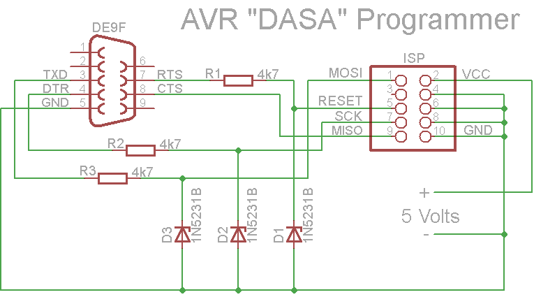
I went back to the drawing board and this time settled on a serial programmer that I could build with what I had on hand augmented with some parts from Radio Shack. Using this schematic I found in the adafruit forums.

I modified the design to us a 6 pin isp connector rather than the 10 pin in the schematic. I also built a simple chip cradle with a 6 pin isp connector and a power connector.

Once I had completed building both the programmer and the chip cradle and checking them out with the multi-meter I plugged it in and…

Nothing. Avrdude running on the PC didn’t see the atmega chip.

After a good nights rest and some more time with Google I determined that my problem was that, as I was using a pre-loaded Arduino chip that was set to us an external crystal/oscillator that I needed to add one to my chip cradle.

Given the mess of wires connecting all the pins together on the underside of the chip cradle this wasn’t easy. However, soon I had a chip cradle with a socket for an external oscillator. I plugged in the oscillator and…

Nothing. Once again avrdude running on the PC didn’t see the atmega chip. Looking at the oscillator and the socket it appeared that the legs of the oscillator might be thin enough not to be making contact. A slight wiggle of the oscillator and success!

I fixed this problem by soldering the oscillator to 3 pins which fit the socket better and it has been working ever since.

Below are several pictures of the finished product.

As usual I need to thank a number of good people who have been down this path before me for marking the way with their posted results. The adafruit, Sparkfun and Arduino forums were invaluable.

Serial Programmer with DB9 serial connector.

SerialProgrammer1

Serial Programmer with Sparkfun 3.3v/5v regulated power supply attached.

SerialProgrammer2

SerialProgrammer3

Chip cradle with oscillator

SerialProgrammer4

Friday, October 2, 2009

Arduino – Light from Sound

For this project I connected a microphone via an amplifier IC (LM386N) to the Arduino to drive the Sparkfun 8x8 multicolor LED Matrix. The LED was programmed to generate random ranges of colors based on the how loud the sound is.

This week I got in an order that I had been waiting for from Futurlec and therefore I am going to put this project on hold as I have some new components I want to test out.

I am posting this mostly so I will have a record of what I had done that I can come back to.

LEDSound

Below is the amplifier on the breadboard.

LEDSoundBlowup

The code was hacked together quickly from a couple of examples.


//Define the "Normal" Colors
#define BLACK  0
#define RED  0xE0
#define GREEN  0x1C
#define BLUE  0x03
#define ORANGE  REDGREEN
#define MAGENTA  REDBLUE
#define TEAL  BLUEGREEN
#define WHITE (REDGREENBLUE)-0xA0

//Define the SPI Pin Numbers
#define DATAOUT 11//MOSI
#define DATAIN  12//MISO
#define SPICLOCK  13//sck
#define SLAVESELECT 10//ss

//Define the variables we'll need later in the program
char cleardisplay [64];
char n1 = 0;
char reddisplay[64];
char n2 = 0;
char greendisplay[64];
char n3 = 0;
char bluedisplay[64];
char n4 = 0;
char rdisplay[64];
char n5 = 0;

char color;
char clearcnt;

int val;
int amp;
int ledPin = 8;                // LED connected to digital pin 13

void setup() {
  //SPI Bus setup
  //Enable SPI HW, Master Mode, divide clock by 16    
  SPCR = (1<<SPE)(1<<MSTR)(1<<SPR1);    

  //SPI Bus setup

  //Set the pin modes for the RGB matrix
  pinMode(DATAOUT, OUTPUT);
  pinMode(DATAIN, INPUT);
  pinMode(SPICLOCK,OUTPUT);
  pinMode(SLAVESELECT,OUTPUT)

  //Make sure the RGB matrix is deactivated
  digitalWrite(SLAVESELECT,HIGH);

  for(int LED=0; LED<64; LED++){
    cleardisplay[LED] = 0;
    reddisplay[LED] = RED;
    greendisplay[LED] = GREEN;
    bluedisplay[LED] = BLUE;
  }
  color = 0;
  clearcnt = 0;
  pinMode(ledPin, OUTPUT);      // sets the digital pin as output 

  Serial.begin(9600);
  setdisplay(cleardisplay);
}

void loop() {
  val = analogRead(1);
  amp = (val >= 415) ? val - 415 : 415 - val;
  if (amp > 30) {
    digitalWrite(ledPin, HIGH);
    if (amp > 50) {
      if (color != RED) {
        rnddisplay(RED);
        color = RED;
      }
    } else if (amp > 40) {
      if (color != GREEN) {
        rnddisplay(GREEN);
        color = GREEN;
      }
    } else if (amp > 30) {
      if (color != BLUE) {
        rnddisplay(BLUE);
        color = BLUE;
      }
    }
    delay(250);
  } else {
    if (clearcnt > 1) {
      digitalWrite(ledPin, LOW);
      setdisplay(cleardisplay);
      color = 0;
      clearcnt = 0;
    } else {
      clearcnt++;
    }
  }
}

void rnddisplay(char color) {
  for(int LED=0; LED<64; LED++) {
    rdisplay[LED] = random(9) + color;
  }
  setdisplay(rdisplay);
}

void setdisplay(char displaybuf[64]) {
  digitalWrite(SLAVESELECT, LOW);
  for(int LED=0; LED<64; LED++){
    spi_transfer(displaybuf[LED]);
  }
  digitalWrite(SLAVESELECT, HIGH);
} 

//Use this command to send a single color value to the RGB matrix.
//NOTE: You must send 64 color values to the RGB matrix before it displays an image!

char spi_transfer(volatile char data) {
  SPDR = data;                    // Start the transmission
  while (!(SPSR & (1<<SPIF))) {   // Wait for the end of the transmission
  };
  return SPDR;                    // return the received byte
}

Sunday, September 20, 2009

Arduino – Breadboard Arduino

As I have said in earlier posts I have been working with Arduino for the last several months. My latest project was to take the ATmega328 chip and assemble a very basic Arduino on a breadboard.

Using various sources found using Google I was able to assemble the breadboard Arduino in an evening and get it running a basic blink program.

ArduinoBreadboard

I found several excellent sources for parts and information which I pass along below:

Once I got all the parts and pieces the project was easy to assemble and get running. I was also able to combined this with the power supplies I built earlier to have a free standing finished product.

Monday, September 7, 2009

Simple 5V Regulated Power Supply Projects

Spent this Labor Day Weekend on a number of projects around the house but still had some time to undertake a couple of simple electronics projects.

The first project was to bread board a simple 5V regulated power supply using parts from Radio Shack and schematics from a couple of helpful websites found via Google.

The end result was a hybrid using the diagram below from http://www.tkk.fi/Misc/Electronics/circuits/psu_5v.html

and the schematic below from the Sparkfun Embeded Electronics Tutorial at http://www.sparkfun.com/commerce/tutorial_info.php?tutorials_id=57

http://www.sparkfun.com/images/tutorials/BEE-Lectures/1-PowerSupply/PowerSupply6.jpg

My design didn’t include the diode or the switch as the Sparkfun design does but did include the 0.1uF capacitor and the LED/resistor. The Sparkfun tutorial also included a diagram of the pinout for the 7805.

http://www.sparkfun.com/images/tutorials/BEE-Lectures/1-PowerSupply/LM7805-Pinout.jpg

The second project was to assemble the Sparkfun Breadboard Power Supply 5V/3.3V (Part No: PRT-00114) http://www.sparkfun.com/commerce/product_info.php?products_id=114 which arrived during the week.

clip_image001[4]

The assembly was a breeze and took less than an hour.

A word of thanks to the folks at Sparkfun for all the good information on their website, the wonderful products they make available and for the speed with which they get things out the door. I have now ordered from them twice and both times have used the USPS Priority shipping option and gotten my order the in three days of placing it.

Friday, August 21, 2009

Arduino – Amplified Speaker Project

I have been playing around with the Arduino for a couple of months. The Arduino is an inexpensive open-source electronics prototyping platform (http://www.arduino.cc/. The compilation below represents a very simple project to connect an amplified speaker to the Arduino.

The amplifier I used for this project is an LM386. The LM386 is a power amplifier designed for use in low voltage applications. It ant the other parts needed for this project , capacitors, resistors and a speaker, can be purchased at Radio Shack.

This example makes use of a Sound Hello World sketch by David Fowler to generate tones.

This also represents my first attempt at a circuit schematic using the freeware version of Eagle from CadSoft at http://www.cadsoft.de/.

My hope is that someone will find this useful and will be able to follow what I have done as I have done following the examples posted by others.

ArduinoAmplifiedSpeaker

ArduinoAmplifiedSpeaker


//Arduino Sound Hello World
//Created by David Fowler of uCHobby.com
//Define the I/O pin we will use for our sound output
#define SOUNDOUT_PIN 9

void setup(void){
  //Set the sound out pin to output mode
  pinMode(SOUNDOUT_PIN,OUTPUT);
}

void loop(void){
  //Generate sound by toggling the I/O pin High and Low
  //Generate a 1KHz tone. set the pin high for 500uS then
  //low for 500uS to make the period 1ms or 1KHz.

  //Set the pin high and delay for 1/2 a cycle of 1KHz, 500uS.
  digitalWrite(SOUNDOUT_PIN,HIGH);
  delayMicroseconds(500);

  //Set the pin low and delay for 1/2 a cycle of 1KHz, 500uS.
  digitalWrite(SOUNDOUT_PIN,LOW);
  delayMicroseconds(500);
}

Wednesday, June 17, 2009

Wii Fun Wrap Up - Part 5 - On Hold For Now

So after almost a month of off and on work, including a couple of very late nights, I have decided to shelve this project since I am not able to get the ease of use or the quality I am looking for.

One area I did not pursue was to hack into the Wii using one of the well publicized hacks and setup a Homebrew Channel. This would allow me to run code on the Wii with the same capabilities as official software. There were several options that looked very promising.

For now, when I want to run slideshows or videos on my TV via the Wii, I will use the Wii's Photo Channel and sneaker.net to move the images and videos from my PC to the Wii.

Wii Fun Wrap Up - Part 4 - Flash Media Players

My next step was to look at Flash Media Players. I wanted to see if there were flash options that would work for both my slideshow needs and also allow me to play family videos.

Back to google which provided me with a number of options. However, I quickly determined that most of these options wouldn't work. The problem is that the Wii's Opera Browser only support Flash version 7 and most of the flash media players required Flash version 8, 9 or even 10.

The problem according to several web sources is that the Adobe SDK required to run flash on platforms other than Windows, Linux or Mac hasn't been released. As a result the Wii Opera browser is not able to run anything above version 7.

I was able to find two FLV Players that ran, to some degree, on Flash 7. The two players were:

My next disappointment was that when I converted the Quick Time Movie generated by my camera to FLV using default settings this quality of the video degraded a great deal.

This led me down a path to better understand FLV and the software options to convert from Quick Time to FLV. After trying a number of different conversion options I finally settled on mencoder which is a video decoding, encoding and filtering tool from the OpenSource MPlayer project at:

It took me a while to settle on a set of conversion parameters but finally after much trial and error I found a set that produced nearly the same quality video.

Unfortunately, when I displayed the newly created FLV video using either FLV Player or JW FLV Player on the Wii the video would hang and/or stutter. The Wii appeared to lack the power to display the video acceptably.

I went back to the drawing board but was not able to come up with a combination that produced a video that looked acceptable on the Wii.

Tuesday, May 26, 2009

Wii Fun Wrap Up - Part 3 - Javascript/Ajax Slideshow Software

I started this activity by returning to google and doing a number of searches for javascript slideshows, javascript image gallary, ajax slideshow and finally ajax image gallary.

There were several sites that came back with 20 to 30 different options. Most were oriented towards displaying a gallery of images on a traditional website and were more complex than what I was looking for.

After much searching and reading I settled on the ones listed below and set them up to test from the Wii.

  1. Highslide
  2. Lightview
  3. Google
  4. Floatbox
  5. dojo.image.SlideShow
  6. Slideshow2
  7. Simple Controls Gallery

Generally my experiences were not as favorable as I had hoped. Several of the routines didn't work while others had some quirk that made them less than optimal.

One of the more unfortunate problems I ran into was that the Wii would issue a sound confirmation when it finished loading images. This along with the blue status bar was distracting.

Highslide

Available from: http://highslide.com/.

This software worked but the controls were awkward.

Lightview

Available from: http://www.nickstakenburg.com/projects/lightview/

I wasn't able to get this software to work on the Wii. The first time a series of images are loaded they don't display right. The next time they do.

Google

Available from: http://www.google.com/uds/solutions/slideshow/helloworld.html

This software worked but requires that images be on a server that is publicly accessible to the Internet. As I was looking for an easy way to pull photographs from my own internal server this wasn't going to work for me.

Floatbox

Available from: http://randomous.com/floatbox/home

I wasn't able to get this software to work on the Wii.

Dojo

Available from: http://www.dojotoolkit.org/

The dojo routine worked as long as you used v1.1.1. The Dojo library doesn't appear to work on the Wii's Opera Browser for any version of Dojo after v1.1.1. This caused some problems as the dojo.image.SlideShow in v1.1.1 didn't work quite right. This was fixed by taking the slideshow widget from a later verison of Dojo and running it with an earlier version of the library. Not something I would recommend but it worked. Also, the transitions were not smooth.

Slideshow2

Available at http://www.electricprism.com/aeron/slideshow/

This software is built on Mootools v1.2. I wasn't able to get this software to work on the Wii.

Simple Controls Gallery

Available at http://www.dynamicdrive.com/dynamicindex4/simplegallery.htm

This software appears to work but I didn't spend too much time with it.

After testing these applications I moved on to see what I could do from a flash perspective.

Monday, May 11, 2009

Wii Fun Wrap Up - Part 2 - Package Solutions

Based on my decision to pursue web based media servers I narrowed my Google search criteria and came up with the following candidates:

Wii Media Center X

Written in java by Red Kawa available at http://www.redkawa.com/mediacenters/wiimediacenterx/.

This software is free but is listed as Alpha or Early Alpha and has not been actively developed since Dec 2007.

Orb

A service available at www.orb.com which consists of software that you load on your PC which then sends the pictures, music or video to servers at orb which then stream it back to your Wii.

Makes use of the Flash 7 player in Opera on the Wii.

Tversity

Available from http://tversity.com/. This software allows you to stream pictures, music, videos and Internet content from a PC to your Wii.

An interesting note is that tversity is built from open source but is not open source itself. It is free to home users with an option to upgrade to a Pro version.

Makes use of the Flash 7 player built into the Opera browser on the Wii.

X-oom

X-oom Media Center for the Wii software costs $40 and is available at http://www.x-oom.com/usa/index.html. It looks to allow access to the following media files: MP3, WMA, OGG, DivX®, Xvid, MPEG2, MPEG4, WMV, JPG, BMP etc.

Wiideo Center

This project hosted at SourceForge was updated as recently as Dec 2008. It is located at http://wiideocenter.sourceforge.net/wiki/index.php/Main_Page. The software uses mencoder from the mplayer project to encode source media as flash and then download to the Wii utilizing the Opera Flash 7 player.

WiiCR

This project is also hosted at SourceForge but hasn't been updated since Feb 2007 and there has been no activity since Dec 2007.

This is by no means a complete list but rather the software I looked more closely at. Where they existed I looked at the feature sets, looked over the screenshots and read what documentation existing. I even installed it Tversity.

I didn't find any significant endorsements for any of the solutions. The one that looked the most interesting was the orb solution but I didn't really want deal with my content being hosted through someone else's server. In the end I decided to move on.

My next step was to look and see what existed in the way of javascrip/ajax slideshow components that would meet my requirements.