Wednesday, October 30, 2013

openFrameworks / pcDuino MFB Update 1

I am in the process of updating openFrameworks for pcDuino MFB which provides support for openFrameworks on the pcDuino using the Mali frame buffer.  I have setup a new repository based on the latest openFrameworks release and have applied the pcDuino Mali frame buffer changes that I developed last spring.  The latest openFramework release has incorporated the Raspberry Pi changes which the pcDuino changes are patterned after.

The new repository and the appropriate branch can be found at: https://github.com/digitalhack/pcDuino-openFrameworks/tree/pcDuino-dev

The repository has the changes in it and I have successfully compiled several of the examples and several of my own test programs.  What I haven’t tested is the install process.  I hope to get to that over the next week or so.

If you give it a try I would be interested in hearing from you (leave a comment) and if you find something that doesn’t work please put an issue in for the repository.

Quick Note - pcDuino - Changing mali_debug_level

Create a conf file for mali in /etc/modprobe.d with one line in it.

cat > /etc/modprobe.d/mali.conf
options mali mali_debug_level=2
^D

I had recently run into an issue where the rsyslogd process was chewing up about 75% of the CPU when I was using the mali driver for GLES2 support. I found out that the mali_debug_level was set to 10. As a result there was a significant amount of messages being generated by the driver. I changed the mali-debug_level to 2 and the high utilization and the messages went away.

I believe this will still get you critical and error messages.

Related commands:

  • To list settable options for a module use: modinfo <module>
  • If module isn’t loaded you can do modprobe <module> [<parameter>=<value>]
  • To determine active value look in /sys/module/<module>/parameters

Thursday, September 12, 2013

pcDuino - Interrupt Tutorial

This is the latest installment of my series of pcDuino tutorials.  This tutorial will show you how to setup and program the pcDuino to respond to an external interrupt.

This assumes that you have a basic working knowledge of the pcDuino and Linux.  It builds upon the pcDuino – Blink Totorial.

For this tutorial you will need the following items:

  1. A pcDuino running the 20130531 Ubuntu image.
  2. A breadboard.
  3. A button such as the Mini Push Button Switch sold by Sparkfun.
  4. Three jumper wires.
  5. A 10K ohm resistor.
  6. The source code below for building interrupt.c.

DSCF4974

Hardware Setup

The setup for this is simple.  You connect one end of the switch to the 3.3V pin on the pcDuino.  You connect the other end of the switch to GPIO2 pin on the pcDuino and to ground through the 10K resistor.  The 10K resistor as it is connected to ground is a pull-down resistor.  It keeps the signal at 0V when the switch is open.  If a pull-up or pull-down resistor was not used the signal would float which could cause intermittent interrupts when one was not signaled.

image

The pins used are shown by the red arrows in the board diagram above.

Interrupt Program

An interrupt is described in Wikipedia as a signal to the processor emitted by hardware or software indicating an event that needs immediate attention.  In this tutorial we are working with a hardware interrupt. 

The pcDuino is setup with two pins that can be used for interrupts: GPIO2 and GPIO3.  The program is written to use SWIRQ_PIN1 and GPIO2.  However, SWIRQ_PIN2 is also define which corresponds to GPIO3.

The way the program works is that when the switch is opened gpio pin 2 is is connected to ground at 0V.  When the switch is pushed it connects 3.3V to gpio pin 2 which is read by the system and results in an interrupt service routine (ISR) being called if one is defined.

There are 5 types of interrupts:

  1. Rising – called when the signal goes from low to high.
  2. Falling – called when the signal goes from high to low.
  3. High – called when the signal is high.
  4. Low – called when the signal is low.
  5. Change – called when the signal goes from low to high and then again when it goes from high to low.

interrupt.c

#include <stdio.h> 
#include <signal.h>   
#include <stdlib.h>    
#include <inttypes.h>    
#include <sys/ioctl.h>    
#include <fcntl.h>
// sw_interrupt must be loaded.  
// if it isn't load using:
// modprobe sw_interrupt

// Data structure for defining an interrupt on the pcDuino   
typedef struct swIRQ {    
    uint8_t channel;    
    int mode;    
    int pid;    
} swIRQt,*irqSWp;

// Pseudo device for controlling interrupts   
static const char *swirq_dev = "/dev/swirq";

#define SWIRQ_START   (0x201)   
#define SWIRQ_STOP    (0x202)    
#define SWIRQ_SETPID  (0x203)    
#define SWIRQ_ENABLE  (0x204)    
#define SWIRQ_DISABLE (0x205)

#define SWIRQ_RISING  (0x00)   
#define SWIRQ_FALLING (0x01)    
#define SWIRQ_HIGH    (0x02)    
#define SWIRQ_LOW     (0x03)    
#define SWIRQ_CHANGE  (0x04)

#define SWIRQ_PIN1    (0x0)   
#define SWIRQ_PIN2    (0x1)

int main(int _argc, char **_argv) {   
  int fd;    
  int ret;    
  uint8_t swIrqNum = 0;    
  swIRQt swIrqCfg;    
 
  // Define ISR    
  int irqPin1Cnt = 0;    
  int irqPin1Func (void) {    
    irqPin1Cnt++;    
  }

  // Attach the ISR to the USR1 signal which is triggered by the OS when the interupt is signaled.   
  signal(SIGUSR1, (void (*) (int))irqPin1Func);

  // Setup to use pin1 / gpio2 when the signal goes from low to high.   
  swIrqCfg.channel = SWIRQ_PIN1;    
  swIrqCfg.mode = SWIRQ_RISING;    
  swIrqCfg.pid = getpid();    
  swIrqNum = SWIRQ_PIN1;    
 
  // Connect a file descriptor to the pseudo device used to control interrupts    
  fd = open(swirq_dev, O_RDONLY);    
  if ( fd < 0 ) {    
    printf("open swirq device fail");    
    exit(0);    
  }    
 
  // Disable interrupts using pin1 / gpio2    
  ret = ioctl(fd, SWIRQ_STOP, &swIrqNum);    
  if (ret < 0) {    
    printf("can't set SWIRQ_STOP");    
    exit(0);    
  }    
 
  // Configure pin1 / gpio2 interrupts    
  ret = ioctl(fd, SWIRQ_SETPID, &swIrqCfg);    
  if (ret < 0) {    
    printf("can't set SWIRQ_SETPID");    
    exit(0);    
  }    
 
  // Enable interrupts on pin1 / gpio2    
  ret = ioctl(fd, SWIRQ_START, &swIrqNum);    
  if (ret < 0) {    
    printf("can't set SWIRQ_START");    
    exit(0);    
  }    
 
  // Disconnect from the pseudo device    
  if (fd) close(fd);    

  // Loop forever. Print out the counter when the ISR has been called.    
  int oldValue = 0;    
  while (2>1) {    
    if (oldValue != irqPin1Cnt) {    
      printf("irqPin1Funct: %d\n", irqPin1Cnt);    
      oldValue = irqPin1Cnt;    
    }    
  }    
}

Program Setup

Using the editor of your choice or the command “cat > interrupt.c” you will need to get the program on to your pcDuino.  See the Blink Tutorial for screen shots on how to do this.

Next you will need to load the appropriate driver if it isn’t already loaded when you boot your system.  You can check using the lsmod command and then load the driver using “sudo modprobe sw_interrupt” again there are screenshots of this in the Blink Tutorial.

Next compile your program using “gcc interrupt.c –o interrupt” and then run it using “./interrupt”.  When you press the button you should get a number printed on your screen.  You will need to use ctrl-c to exit the program.

Acknowledgements

Thanks to the folks at Sparkfun and their great Getting Started with pcDuino for getting me started with putting this tutorial together.  Also thanks to the folks on the pcDuino website for their support.  Check out the website and forums for more information.

Monday, September 2, 2013

pcDuino - Analog Read Tutorial

This tutorial will show you how to program the pcDuino to read an analog input.

It assumes you have a basic working knowledge of the pcDuino on Linux.  It builds upon the pcDuino – Blink Tutorial.

For this tutorial you will need the following items:

  1. A pcDuino running the 20130531 Ubuntu image with ssh.
  2. A breadboard.
  3. A potentiometer.
  4. Three wire jumpers.
  5. The source code below for analog.c

DSCF4970

Hardware Setup

A potentiometer also known as a pot has three terminals.  These terminals connect to the the input voltage, the input channel and ground.  The input channel terminal is connected inside the pot to a wiper that moves across resistive material in the pot.  The closer it is to the terminal with ground connected the lower the voltage and the closer it is to the terminal with the input voltage higher the voltage is.

I used a 10K Ohm breadboard compatible potentiometer similar to the one in the picture below.

From left to right on the breadboard in the picture above are connected: ground, ADC2, and 3.3V.

image

At this point you are ready to power up your pcDuino.

Analog Read Program

To read an analog pin you just need to open a special file and then read the file.

The file is /proc/adc# where the # is replaced with 0 – 5 depending on the pin you are using.  ADC0 and ADC1 work with voltages from 0V to 2V and have 6 bits.  This means that you are going to be reading values from 0 to 63.  ADC1 – ADC5 work with voltages from 0V to 3.3V and have 12 bits which means you will read values from 0 – 4095.

When /proc/adc# is read it returns the following string: adc#:<value> where # is the adc pin 0 to 5 and value is 0 to 63 for ADC0 and ADC1 and 0 to 4095 for ADC2 to ADC5.

analog.c

#include <stdio.h>   
#include <fcntl.h>

#define ADEV "/proc/adc2" int main(void) { int aPin = open(ADEV, O_RDONLY); while (2 > 1) { char tBuf[16]; // set to start of file lseek(aPin, 0, SEEK_SET); // read adc data int ret = read(aPin, tBuf, sizeof(tBuf)); // convert adc data to a value. int aVal = atoi(tBuf+5); printf("%d\n", aVal); } }

Program Setup

Using the editor of your choice or the command “cat > analog.c” you will need to get the program on to your pcDuino.  See the Blink Tutorial for screen shots on how to do this.

Next you will need to load the appropriate driver if it isn’t already loaded when you boot your system.  You can check using the lsmod command and then load the driver using “sudo modprobe adc” again there are screenshots of this in the Blink Tutorial.

Next compile your program using “gcc analog.c –o analog” and then run it using “./analog”.  You should get a series of numbers printed on your screen.  These numbers should change when you rotate the pot attached to the pcDuino.

Acknowledgements

Thanks to the folks at Sparkfun and their great Getting Started with pcDuino for getting me started with putting this tutorial together.  Also thanks to the folks on the pcDuino website for their support.  Check out the website and forums for more information.

Wednesday, June 26, 2013

pcDuino - Blink Tutorial

This tutorial will show you how to program the pcDuino to flash an LED on a connected breadboard.

It assumes you have a basic working knowledge of the pcDuino and Linux.

For this tutorial you will need the following items:

  1. A pcDuino running the 20130531 Ubuntu image with ssh.
  2. A breadboard.
  3. An LED.
  4. A 100ohm resistor
  5. Two wire jumpers.
  6. The source code below for blink.c

image

Hardware Setup

The hardware setup for this tutorial is pretty easy. 

Take the LED and plug the negative or cathode lead into the ground strip on you breadboard.  This lead is the shorter of the two leads and comes from the side if the LED that is flat.

Plug the positive or anode lead into a row on the body of the breadboard.

Take the resistor and plug on end into the same row as the positive lead of the LED and plug the other lead into another row on the body of the breadboard.

You should end up with something that is close to the picture below but without the jumpers.

image

Take your two jumpers and connect one into the ground strip and the other into the row as the resistor lead (and only the resistor lead) in it.  I used a black jumper for the ground and a green one for the signal.

Next you will need to connect the other ends of the jumpers to the pcDuino.  This should be done before power the pcDuino on.

image

At the bottom of the pcDuino board there are two rows of pins.  One row of pins is right next to the edge of the board and the other is on the other side of the first row.  We are going to be using pins in the row right next to the edge of the board.

With the board oriented so that the host usb ports are to the left and the hdmi / ethernet jack are to the left we want to connect the ground jumper to the fourth (4th) in from the right and the signal jumper to the fifth (5th) pin.  This will connect the ground jumper to a ground pin and the signal jumper to the pin assigned to gpio13.

At this point you are ready to power up your pcDuino to get the program loaded and compiled.

blink Program

Blinking an LED with the pcDuino is pretty simple.  On the pcDuino the pin we connected our signal jumper to is known as a gpio pin.  This stands for “general purpose IO”.

On the pcDuino the gpio pins are accessed using two pseudo files. 

The first “file” is /sys/devices/virtual/misc/gpio/mode/gpio13.  This “file” is used to set the mode of the pin.  There are three possible modes: input, output, and input with pull up resistor.  We will be using the output mode.

The second “file” is /sys/devices/virtual/misc/gpio/pin/gpio13.  This “file” is used to set the value of the pin.  Pins can be set to low or zero by writing a “0” to this “file”.  Pins can be set to high or one by writing a “1” to this “file”.

With our blink example writing a “1” to the value pin will light the LED and writing a “0” will turn off the LED.

The program below turns the LED on, waits two seconds, turns the LED off, waits two seconds and then starts the whole process over until it has been done 10 times.

blink.c

#include <fcntl.h>
#include <stdio.h>
#include <string.h>
#include <unistd.h>

#define pinModePath "/sys/devices/virtual/misc/gpio/mode/gpio13"
#define pinDataPath "/sys/devices/virtual/misc/gpio/pin/gpio13"

int main(void) {

  int pinMode = open(pinModePath, O_RDWR);
  int pinData = open(pinDataPath, O_RDWR);

  // "0" - pin INPUT
  // "1" - pin OUTPUT
  // "8" - pin INPUT with pull-up resistor
  write(pinMode, "1", 1);
  
  // "0" - LOW
  // "1" - HIGH
  write(pinData, "1", 1);
  
  int i;
  for (i=0; i < 10; i++) {
    write(pinData, "1", 1);
    usleep(2000000);
    write(pinData, "0", 1);
    usleep(2000000);
  }
}

Program Setup

Start by connecting to your pcDuino via ssh. I am connecting from a PC running Windows 7 Pro 64bit and using a KiTTY as my ssh program. KiTTY is a form of PuTTY v0.62 which has some added features I like. Any ssh program should work.

Login into any user on your pcDuino.  I used the default ubuntu user which if you haven’t changed it (which you should have) has a default password of ubuntu.

image

I would suggest making a subdirectory to build your program in.  This isn’t required but is a nice way when you get to more complicated programs of keeping everything together.  I used tutorial and then changed directory to tutorial.

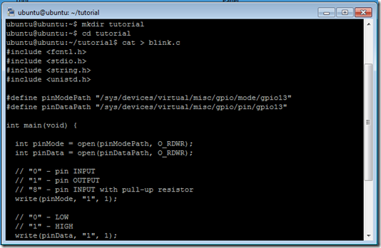
The next step we will do will allow you to copy the source code from this post and paste it into a file on the pcDuino.  Start by copying the source code for blink.c posted above.  The go back to your ssh windows type “cat > blink.c” and return.  This will leave you with a blinking cursor one line below the cat command.

image

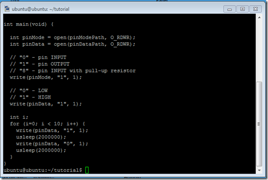
Next move your mouse pointer into the ssh window and paste the source code into the window.  Once the source code has finished “typing” into your window press control-D (while holding down the control key press and release the D).  This will bring you back to the prompt.  Most ssh programs I have used will automatically paste what is in the paste buffer into the window if you select the right mouse button.
image

image

If this process of entering the source code doesn’t work you can always manually type the source code into a file using a text editor on the linux system.  This isn’t that difficult to do but is beyond the scope of this tutorial.

Next you should make sure that the gpio drivers are loaded on your system.  This is done by running the “lsmod” command.  As shown in the window below there should be a line for hardwarelib followed by gpio.  If that line doesn’t exist you can use the privileged modprobe command to load the driver.  This is done by typing “sudo modprobe gpio”.  Once this has been done you can rerun the lsmod command and you should see the gpio’s listed.

image

You are now ready to compile your program and run it.  To compile and link you program you should use “gcc blink.c –o blink”.  The system will compile your program in file blink.c and save the executable in a file called blink.  To run the program you enter ./blink and the LED on your breadboard should begin to blink.

image

Thanks to the folks at Sparkfun and their great Getting Started with pcDuino for getting me started with putting this tutorial together.  Also thanks to the folks on the pcDuino website for their support.  Check out the website and forums for more information.

Wednesday, June 19, 2013

openFrameworks / pcDuino

After a couple of months of on and off again work building on what was started by bakercp and others I have had some success in getting openFrameworks running on the pcDuino.

I am able to compile the openFrameworks library, compile openFrameworks programs and run them.

With the steps below you should be able to compile a pcDuino Hello World application similar to the one for the Raspberry Pi.

Setup the pcDuino to use Mali Framebuffer

git clone https://github.com/digitalhack/sunxi-mali.git
cd sunxi-mali
git submodule init
git submodule update
make config VERSION=r3p0 ABI=armhf EGL_TYPE=framebuffer
make
make install
make test
stop lightdm
./test/test


At this point you should see something that looks like this

MaliTestTraiangle

Setup openFrameworks

git clone https://github.com/digitalhack/RaspberryPi-openFrameworks.git
cd RaspberryPi-openFrameWorks
cd scripts/linux/ubuntu_pcduino/
sudo install_dependancies.sh
sudo install_codecs.sh
sudo install_poco_libraries.sh


Compile and run the pcDuino Hello World Program

cd ../apps/devApps/pcDuino_hello_world_gles2
make PLATFORM_VARIANT=pcduino
sudo ./bin/pcDuino_hello_world_gles2


At this point you should see a spinning pcDuino board on a yellow background.

pcDhw
I haven't had time for much testing. Besides the Hello World program I have successfully tested several of the examples. I hope to have some time for more testing over the next couple of days.

Saturday, June 1, 2013

It Worked For Me - pcDuino

The March 1st Sparkfun New Product Friday post included a linux development board that peaked my interest.  The pcDuino was described in the post as something that folks who were looking at the Raspberry Pi but wanted a bit more should check out.  The post went on to say that besides running Ubuntu and Android you could connect Arduino shields to it.  I was hooked and by the end of the day had placed my order. A week later a red Sparkfun box showed up at my doorstep.

After unboxing it I connected a keyboard, a mouse, an HDMI cable and my ethernet switch and applied power. I was rewarded a few moments later with an Ubuntu 12.10 LXDE window on my monitor. Getting this far was a no brainer.

My next step was to get it to connect to my home network using the wireless dongle that I had ordered with the board. Unfortunately, this didn't go as well. At the time the image loaded in NAND didn't support the chipset used on the wifi dongle.

Fast forward...

I have been working with the pcDuino for about three months. For me the pcDuino has been very DIY and therefore has been an interesting (sometimes frustrating) learning experience.

To aid with the DIY process there is a lot of good information. Sparkfun has tutorials. There is a support website for the pcDuino that contains informational posts, software images, a wiki and forums. Finally there is a pcDuino repository on github.

Sparkfun Tutorials
pcDuino website
pcDuino on github

When I got my pcDuino these sites were much less mature than they are now and didn't have a whole lot of information. However, I found that there are a number of Allwinner A10 based development boards and a number of inexpensive A10 based tables made in China. As a result there is a small (compared to the RPi community) but very active user community.

Googling around the internet I found a number of sources of detailed information and source code:

Forums at doozan.com - these forums are a treasure trove of information. The information is a bit dated but still very useful.

rhombus-tech - this is another site that has a lot of good A10 based information.

linux-sunxi - this site is the heart of the community and along with the linux-sunxi google group is the best source of information and software.

The lack of out of the box support for the wifi dongle led me to attempt to load the driver source and compile it. Unfortunately, the pcDuino image didn't contain the necessary header files to be able to compile the driver so I was stuck.

After looking a bit further it appeared that if I compiled my own kernel I could include the needed wifi driver. It also looked like there were several other options that I was looking for that were available from the repositories at linux-sunxi. I ended up setting up a cross compile environment on Ubuntu and building my own kernels. Building my own kernels enabled me to finally get the wifi card working and to get bluetooth working.

Over the past three months the pcDuino community has grown. The community, along with the folks that developed the pcDuino, continue to move things forward. There have been several new software images released by the pcDuino folks, some software ported to the platform, a number of tutorials developed and informational posts that apply specifically to the pcDuino.

Below is setup I I have been using. I attached my pcDuino to a piece of plexiglass with rubber feet on it to keep it from sliding around. I am using an older Sparkfun 3.3v FTDB Basic board to connect to the pcDuino's serial console and a Manahattan USB hub to connect the wifi card, an IOGear Bluetooth dongle and a keyboard and mouse as well as to supply power to the pcDuino.

Setup

One area that has been challenging is the ability to integrate some of the features that come in the stock software working with custom kernels. There is a lot of discussion as to the cause of this on various websites. It appears that some of the problem is the level of support Allwinner is providing the open source community. However, even with these challenges things have come a long way thanks to a core of very dedicated people.

My experience with the pcDuino has been positive. I would recommend it to anyone who is looking for a moderately powered linux development board for DIY projects as long as they are comfortable with a product that is slightly rough around the edges.

More to come...