Sunday, December 13, 2009

It Worked for Me – FIOS Installation

We recently moved from Comcast to FIOS. The change was sparked by recent changes in Comcast’s cable service. We had been a long time Comcast customer and had a very good experience. However, when I compared bundled offerings from Comcast and Verizon the FIOS bundle came out better.

The week before Thanksgiving I put in a FIOS order and scheduled the installation for the next week. The day before the installation Verizon called to confirm that we would be home during the appointed window. The morning of the installation the Verizon Installer called to let us know that he would be arriving towards the middle of the installation window.

When the installer arrived we reviewed the setup. We looked at where the phone lines came into the house, the cable TV and found an appropriate power outlet that would be able to supply power to the box on the outside of the house.

It was an aerial delivery so shortly after we finished with the review another Verizon person showed up with a bucket truck and between the two Verizon personnel they installed the fiber to the house.

Overall the installation took four or five hours. The installer was very professional and even went to the trouble of having shoe covers for the inside work.

We now have a new box on the outside of the house, two phone lines moved over, three TVs connected and a new wireless Internet firewall/router. With one minor exception all parts of the installation went without a hitch. There was a problem with features on the two telephone lines which were reversed. A follow up email to customer service fixed this within 24 hours.

Two weeks after the install the TV service has been working flawlessly as has the Internet. One of the phone lines still has a problem with call forwarding.

Customizing the setup of the TV remotes and the Internet was easy to do. The Internet firewall/router even has a few bells and whistles that my previous Linksys and DLink boxes did not.

All in all a very good experience…

Time Flies – November 2009

Wow, looking back at my last post I see it was in October. November just flew by. Look for a couple of posts on activities that were squeezed in with everything else:

  • FIOS Migration
  • Garman GPS MAP 60 Acquisition
  • Hacking around with Qt
  • Arduino Robotics

Saturday, October 24, 2009

Arduino – SD Card

This afternoon’s project was to connect an SD card to an Arduino to be able to record log information on the card for later retrieval using a PC.
For the project I used an SD/MMC Mini Board from Futurelec. Futurlec has a number of interesting products which are reasonably priced. The order took a little over a month given the fact that they didn’t have the board in stock and due to international shipping. During the wait the folks at Futurelec were quite responsive to my queries via email.
I was using an atmega328p chip powered at 3.3v with an 8mhz oscillator. This made things easier as I didn’t need to worry about voltage dividers between the microprocessor and the SD card. The hardware I used was rounded out with a 512mb Kodak SD Card I had laying around.
SDCard
For software I used Bill Greiman’s fat16lib which performed flawlessly. I tested my project with fat16info, fat16write and fat16tail with version 17 of the Arduino IDE.
The only problem I had was that I missed that the SD/MMC Mini Board has two pins labeled CD. One is in fact pin 1 from the SD card while the other is Card Detect. Pin 1 from the SD card is clearly labeled as such but I missed it the first time and connected to the other CD.
The pinouts that I used are below for reference:
Arduino Pinsatmega328p PinsDescriptionSD Card PinsSD Description
1016ssel1cd/dat3
1117misi2cmd
1319sck5clk
1218miso7dat0
vcc 3.3vvccvcc 3.3v4vcc 3.3v
gndgndgnd3+6gnd
I want to thank Bill Greiman for the great library he has put together. Also, my thanks to all of you who have posted information about your projects that helped me along.

Friday, October 23, 2009

Arduino – Serial Programmer

I decided that I wanted to experiment at programming the boot loader into chips myself. This started me down an interesting path.

After spending some time with Google and based on what I had around I decided that I would build a parallel programmer. For reference I used the directions on the Arduino site for a parallel programmer.

I modified the design to include a 28 pin dip socket so I would have something to put the chip in. After putting it all together and checking the connections with my trusty multi-media I couldn’t get it to work. I played around with it and with avrdude finally giving up after running out of ideas.

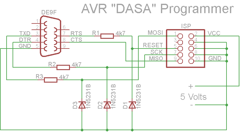
I went back to the drawing board and this time settled on a serial programmer that I could build with what I had on hand augmented with some parts from Radio Shack. Using this schematic I found in the adafruit forums.

I modified the design to us a 6 pin isp connector rather than the 10 pin in the schematic. I also built a simple chip cradle with a 6 pin isp connector and a power connector.

Once I had completed building both the programmer and the chip cradle and checking them out with the multi-meter I plugged it in and…

Nothing. Avrdude running on the PC didn’t see the atmega chip.

After a good nights rest and some more time with Google I determined that my problem was that, as I was using a pre-loaded Arduino chip that was set to us an external crystal/oscillator that I needed to add one to my chip cradle.

Given the mess of wires connecting all the pins together on the underside of the chip cradle this wasn’t easy. However, soon I had a chip cradle with a socket for an external oscillator. I plugged in the oscillator and…

Nothing. Once again avrdude running on the PC didn’t see the atmega chip. Looking at the oscillator and the socket it appeared that the legs of the oscillator might be thin enough not to be making contact. A slight wiggle of the oscillator and success!

I fixed this problem by soldering the oscillator to 3 pins which fit the socket better and it has been working ever since.

Below are several pictures of the finished product.

As usual I need to thank a number of good people who have been down this path before me for marking the way with their posted results. The adafruit, Sparkfun and Arduino forums were invaluable.

Serial Programmer with DB9 serial connector.

SerialProgrammer1

Serial Programmer with Sparkfun 3.3v/5v regulated power supply attached.

SerialProgrammer2

SerialProgrammer3

Chip cradle with oscillator

SerialProgrammer4

Friday, October 2, 2009

Arduino – Light from Sound

For this project I connected a microphone via an amplifier IC (LM386N) to the Arduino to drive the Sparkfun 8x8 multicolor LED Matrix. The LED was programmed to generate random ranges of colors based on the how loud the sound is.

This week I got in an order that I had been waiting for from Futurlec and therefore I am going to put this project on hold as I have some new components I want to test out.

I am posting this mostly so I will have a record of what I had done that I can come back to.

LEDSound

Below is the amplifier on the breadboard.

LEDSoundBlowup

The code was hacked together quickly from a couple of examples.


//Define the "Normal" Colors
#define BLACK  0
#define RED  0xE0
#define GREEN  0x1C
#define BLUE  0x03
#define ORANGE  REDGREEN
#define MAGENTA  REDBLUE
#define TEAL  BLUEGREEN
#define WHITE (REDGREENBLUE)-0xA0

//Define the SPI Pin Numbers
#define DATAOUT 11//MOSI
#define DATAIN  12//MISO
#define SPICLOCK  13//sck
#define SLAVESELECT 10//ss

//Define the variables we'll need later in the program
char cleardisplay [64];
char n1 = 0;
char reddisplay[64];
char n2 = 0;
char greendisplay[64];
char n3 = 0;
char bluedisplay[64];
char n4 = 0;
char rdisplay[64];
char n5 = 0;

char color;
char clearcnt;

int val;
int amp;
int ledPin = 8;                // LED connected to digital pin 13

void setup() {
  //SPI Bus setup
  //Enable SPI HW, Master Mode, divide clock by 16    
  SPCR = (1<<SPE)(1<<MSTR)(1<<SPR1);    

  //SPI Bus setup

  //Set the pin modes for the RGB matrix
  pinMode(DATAOUT, OUTPUT);
  pinMode(DATAIN, INPUT);
  pinMode(SPICLOCK,OUTPUT);
  pinMode(SLAVESELECT,OUTPUT)

  //Make sure the RGB matrix is deactivated
  digitalWrite(SLAVESELECT,HIGH);

  for(int LED=0; LED<64; LED++){
    cleardisplay[LED] = 0;
    reddisplay[LED] = RED;
    greendisplay[LED] = GREEN;
    bluedisplay[LED] = BLUE;
  }
  color = 0;
  clearcnt = 0;
  pinMode(ledPin, OUTPUT);      // sets the digital pin as output 

  Serial.begin(9600);
  setdisplay(cleardisplay);
}

void loop() {
  val = analogRead(1);
  amp = (val >= 415) ? val - 415 : 415 - val;
  if (amp > 30) {
    digitalWrite(ledPin, HIGH);
    if (amp > 50) {
      if (color != RED) {
        rnddisplay(RED);
        color = RED;
      }
    } else if (amp > 40) {
      if (color != GREEN) {
        rnddisplay(GREEN);
        color = GREEN;
      }
    } else if (amp > 30) {
      if (color != BLUE) {
        rnddisplay(BLUE);
        color = BLUE;
      }
    }
    delay(250);
  } else {
    if (clearcnt > 1) {
      digitalWrite(ledPin, LOW);
      setdisplay(cleardisplay);
      color = 0;
      clearcnt = 0;
    } else {
      clearcnt++;
    }
  }
}

void rnddisplay(char color) {
  for(int LED=0; LED<64; LED++) {
    rdisplay[LED] = random(9) + color;
  }
  setdisplay(rdisplay);
}

void setdisplay(char displaybuf[64]) {
  digitalWrite(SLAVESELECT, LOW);
  for(int LED=0; LED<64; LED++){
    spi_transfer(displaybuf[LED]);
  }
  digitalWrite(SLAVESELECT, HIGH);
} 

//Use this command to send a single color value to the RGB matrix.
//NOTE: You must send 64 color values to the RGB matrix before it displays an image!

char spi_transfer(volatile char data) {
  SPDR = data;                    // Start the transmission
  while (!(SPSR & (1<<SPIF))) {   // Wait for the end of the transmission
  };
  return SPDR;                    // return the received byte
}

Sunday, September 20, 2009

Arduino – Breadboard Arduino

As I have said in earlier posts I have been working with Arduino for the last several months. My latest project was to take the ATmega328 chip and assemble a very basic Arduino on a breadboard.

Using various sources found using Google I was able to assemble the breadboard Arduino in an evening and get it running a basic blink program.

ArduinoBreadboard

I found several excellent sources for parts and information which I pass along below:

Once I got all the parts and pieces the project was easy to assemble and get running. I was also able to combined this with the power supplies I built earlier to have a free standing finished product.

Monday, September 7, 2009

Simple 5V Regulated Power Supply Projects

Spent this Labor Day Weekend on a number of projects around the house but still had some time to undertake a couple of simple electronics projects.

The first project was to bread board a simple 5V regulated power supply using parts from Radio Shack and schematics from a couple of helpful websites found via Google.

The end result was a hybrid using the diagram below from http://www.tkk.fi/Misc/Electronics/circuits/psu_5v.html

and the schematic below from the Sparkfun Embeded Electronics Tutorial at http://www.sparkfun.com/commerce/tutorial_info.php?tutorials_id=57

http://www.sparkfun.com/images/tutorials/BEE-Lectures/1-PowerSupply/PowerSupply6.jpg

My design didn’t include the diode or the switch as the Sparkfun design does but did include the 0.1uF capacitor and the LED/resistor. The Sparkfun tutorial also included a diagram of the pinout for the 7805.

http://www.sparkfun.com/images/tutorials/BEE-Lectures/1-PowerSupply/LM7805-Pinout.jpg

The second project was to assemble the Sparkfun Breadboard Power Supply 5V/3.3V (Part No: PRT-00114) http://www.sparkfun.com/commerce/product_info.php?products_id=114 which arrived during the week.

clip_image001[4]

The assembly was a breeze and took less than an hour.

A word of thanks to the folks at Sparkfun for all the good information on their website, the wonderful products they make available and for the speed with which they get things out the door. I have now ordered from them twice and both times have used the USPS Priority shipping option and gotten my order the in three days of placing it.